
AC 80-260V 0-100A ดิจิตอล Multifunction Meter วัตต์โวลต์ Amp Current โมดูล PZEM-004T สำหรับ Arduino TTL COM2 \ COM3 \ COM4


| หมวดหมู่ | อุปกรณ์ไฟฟ้า และ งานไฟฟ้าบ้าน |
| ราคา | 350.00 บาท |
| ขนาด | 100Amp. |
| สถานะสินค้า | พร้อมส่ง |
| สภาพ | สินค้าใหม่ |
| ลงสินค้า | 26 พ.ค. 2565 |
| อัพเดทล่าสุด | 4 ส.ค. 2565 |
| จำนวน | ชิ้น |
หยิบลงตะกร้า

รายละเอียดสินค้า
ภาพรวม
เอกสารนี้อธิบายข้อมูลจำเพาะของ PZEM-004T AC โมดูลการสื่อสาร,
โมดูลใช้สำหรับวัด แรงดันไฟฟ้า AC , กระแสไฟฟ้า, ความถี่, Power
Factor และ Active Energy , ข้อมูลอ่านผ่าน TTL อินเทอร์เฟซ
PZEM-004T-100A: ช่วงการวัด100A (หม้อแปลงภายนอก)
1.ฟังก์ชั่น Description
1.1แรงดันไฟฟ้า
1.1.1วัดช่วง: 80 ~ 260V
1.1.2ความละเอียด: 0.1V
1.1.3การวัดความถูกต้อง: 0.5%
1.2 กระแสไฟฟ้า
1.2.1 ค่าเริ่มต้นที่วัด current: 0.02A(PZEM-004T-100A)
1.2.2 ความละเอียด: 0.001A
1.2.3 การวัดความถูกต้อง: 0.5%
1.3 Active Power
1.3.1ช่วงการวัด: 0 ~ 23kW(PZEM-004T-100A)
1.3.2 ค่าเริ่มต้นที่วัด Power: 0.4W
1.3.3 ความละเอียด: 0.1W
1.3.4 รูปแบบการแสดงผล:
<1000W, จอแสดงผล One decimal, เช่น: 999.9W
≥ 1000W, จอแสดงผลเท่านั้น integer, เช่น: 1000W
1.3.5 การวัดความถูกต้อง: 0.5%
1.4 Power Factor
1.4.1 ช่วงการวัด: 0.00 ~ 1.00
1.4.2 ความละเอียด: 0.01
1.4.3 การวัดความถูกต้อง: 1%
1.5 ความถี่
1.5.1 ช่วงการวัด: 45Hz ~ 65Hz
1.5.2 ความละเอียด: 0.1Hz
1.5.3 การวัดความถูกต้อง: 0.5%
1.6 Active Energy
1.6.1 ช่วงการวัด: 0 ~ 9999.99kWh
1.6.2 ความละเอียด: 1Wh
1.6.3 การวัดความถูกต้อง: 0.5%
1.6.4 รูปแบบการแสดงผล:
<10kWh, หน่วยแสดงผลคือ WH (1kWh = 1000Wh) เช่น: 9999Wh
≥ 10kWh จอแสดงผลหน่วย kWh, เช่น: 9999.99kWh
1.6.5 รีเซ็ตพลังงาน: ใช้ซอฟต์แวร์รีเซ็ต
1.7 Power ALARM
Active Power เกณฑ์สามารถชุดเมื่อวัด Active Power สูงกว่าเกณฑ์,
การแจ้งเตือน
1.8 อินเทอร์เฟซการสื่อสาร RS485 interface.
2 โปรโตคอลการสื่อสาร
2.1 Physical Layer Protocol
Physical Layer ใช้ UART ไปยัง RS485อินเทอร์เฟซการสื่อสาร
อัตราการส่งข้อมูล9600, 8ข้อมูล bits, 1บิตหยุดไม่มี Parity
2.2 Application Layer Protocol
การประยุกต์ใช้ชั้นใช้ Modbus-RTU Protocol TO communicate. ปัจจุบันเท่านั้น
รองรับฟังก์ชั่นรหัสเช่น0x03 (อ่าน Holding ลงทะเบียน) 0x04 (อ่านอินพุตลงทะเบียน), 0x06
(ถ่ายทอดเดียวลงทะเบียน), 0x41 (Calibration), 0x42 (รีเซ็ต Energy) ฯลฯ.
0x41ฟังก์ชั่นรหัสสำหรับใช้ภายใน (ที่อยู่สามารถเท่านั้น0xF8), ใช้สำหรับโรงงาน
สอบเทียบและกลับโรงงาน Maintenance โอกาส, หลังฟังก์ชั่นรหัสเพิ่ม16-bit
รหัสผ่านรหัสผ่านเริ่มต้นคือ0x3721
The ที่อยู่ช่วงทาส0x01 ~ 0xF7. The ที่อยู่0x00เป็นออกอากาศ
ที่อยู่, ทาสไม่ต้องตอบกลับ MASTER. The ที่อยู่0xF8ใช้เป็นทั่วไป
ที่อยู่นี้ที่อยู่สามารถเท่านั้นเดี่ยว-Slave สภาพแวดล้อมและสามารถใช้สำหรับสอบเทียบ
ฯลฯการทำงาน
2.3อ่านการวัดผลการค้นหา
Command รูปแบบ master อ่านการวัดผลคือ (รวม8ไบต์):
Slave ที่อยู่ + 0x04 + ลงทะเบียนที่อยู่ไบต์สูง + ลงทะเบียนที่อยู่ไบต์ต่ำ + หมายเลข
ของ Register ไบต์สูง + จำนวน Registers ไบต์ต่ำ + CRC Check ไบต์สูง + CRC Check
ไบต์ต่ำ.
Command รูปแบบตอบกลับจาก Slave แบ่งออกเป็น2ชนิด:
ที่ถูกต้องเมื่อ: Slave ที่อยู่ + 0x04 + จำนวน Bytes + ลงทะเบียน1ข้อมูลไบต์สูง +
ลงทะเบียน1ข้อมูลไบต์ต่ำ +... + CRC Check ไบต์สูง + CRC Check ไบต์ต่ำ
ข้อผิดพลาดเมื่อ: Slave ที่อยู่ + 0x84 + ผิดปกติรหัส + CRC check ไบต์สูง + CRC check
ไบต์ต่ำ
ผิดปกติรหัสวิเคราะห์ดังต่อไปนี้ (เดียวกันด้านล่าง)
⚫0x01,Illegal ฟังก์ชั่น
⚫0x02,Illegal ที่อยู่
⚫0x03,Illegal ข้อมูล
⚫0x04,Slave ข้อผิดพลาด
The Register of การวัดผลลัพธ์จัดเป็นตารางต่อไปนี้
ตัวอย่างเช่น MASTER ส่งต่อไปนี้ Command (CRC check รหัสเปลี่ยนโดย
0xHH และ0xLL เดียวกันด้านล่าง)
0x01 + 0x04 + 0x00 + 0x00 + 0x00 + 0x0A + 0xHH + 0xLL
แสดงว่า Master ความต้องการอ่าน10 Registers พร้อม Slave ที่อยู่0x01และเริ่มต้น
ที่อยู่ของ Register คือ0x0000
ที่ถูกต้องตอบกลับจาก Slave คือดังต่อไปนี้:
0x01 + 0x04 + 0x14 + 0x08 + 0x98 + 0x03 + 0xE8 + 0x00 + 0x00 + 0x08 + 0x98 + 0x00 +
0x00 + 0x00 + 0x00 + 0x00 + 0x00 + 0x01 + 0xF4 + 0x00 + 0x64 + 0x00 + 0x00 + 0xHH + 0xLL
ด้านบนข้อมูลแสดง
⚫แรงดันไฟฟ้า0x0898แปลงเป็น decimal 2200, จอแสดงผล220.0V
⚫ปัจจุบันคือ0x000003E8แปลงเป็น decimal 1000, จอแสดงผล1.000A
⚫กำลังไฟ0x00000898แปลงเป็น decimal 2200, จอแสดงผล220.0W
⚫Energy 0x00000000แปลงเป็น decimal 0, จอแสดงผล0Wh
⚫ความถี่0x01F4แปลงเป็น decimal 500, จอแสดงผล50.0Hz
⚫Power Factor 0x0064แปลงเป็น decimal 100, จอแสดงผล1.00
⚫นาฬิกาปลุกสถานะ0x0000, แสดงว่า current Power ต่ำกว่านาฬิกาปลุก Power
เกณฑ์
2.4อ่านและแก้ไข Slave พารามิเตอร์
ปัจจุบันเท่านั้นรองรับอ่านและปรับเปลี่ยน Slave ที่อยู่และ Power นาฬิกาปลุกเกณฑ์
The Register จัดเป็นตารางต่อไปนี้
Command รูปแบบ master อ่าน Slave พารามิเตอร์และอ่านการวัด
ผลลัพธ์เดียวกัน (descrybed ในรายละเอียดส่วน2.3) เพียงเปลี่ยนฟังก์ชั่นรหัส
0x04 TO 0x03.
Command รูปแบบ master เพื่อแก้ไข Slave พารามิเตอร์คือ (รวม8ไบต์):
Slave ที่อยู่ + 0x06 + ลงทะเบียนที่อยู่ไบต์สูง + ลงทะเบียนที่อยู่ไบต์ต่ำ + Register
มูลค่าไบต์สูง + ลงทะเบียนมูลค่าไบต์ต่ำ + CRC Check ไบต์สูง + CRC Check ไบต์ต่ำ.
Command รูปแบบตอบกลับจาก Slave แบ่งออกเป็น2ชนิด:
ที่ถูกต้อง Response: Slave ที่อยู่ + 0x06 + จำนวน Bytes + ลงทะเบียนที่อยู่ไบต์ต่ำ +
ลงทะเบียนมูลค่าไบต์สูง + ลงทะเบียนมูลค่าไบต์ต่ำ + CRC Check ไบต์สูง + CRC Check ต่ำ
ไบต์
ข้อผิดพลาดเมื่อ: Slave ที่อยู่ + 0x86 + ผิดปกติรหัส + CRC check ไบต์สูง + CRC check
ไบต์ต่ำ.
ตัวอย่างเช่น Master ชุด Slave Power นาฬิกาปลุกเกณฑ์:
0x01 + 0x06 + 0x00 + 0x01 + 0x08 + 0xFC + 0xHH + 0xLL
แสดงว่า Master ความต้องการชุด0x0001ลงทะเบียน (Power นาฬิกาปลุกเกณฑ์) TO 0x08FC
(2300W)
เครื่องคอมพิวเตอร์ของคุณ, ทาสกลับข้อมูลซึ่งส่งจาก MASTER.
ตัวอย่างเช่นราคาต่ำสุด Master ชุดที่อยู่ SLAVE
0x01 + 0x06 + 0x00 + 0x02 + 0x00 + 0x05 + 0xHH + 0xLL
แสดงว่า Master ความต้องการชุด0x0002ลงทะเบียน (Modbus-RTU ที่อยู่) TO 0x0005
เครื่องคอมพิวเตอร์ของคุณ, ทาสกลับข้อมูลซึ่งส่งจาก MASTER.
2.5รีเซ็ตพลังงาน
Command รูปแบบ master RESET ทาส's Energy (รวม4ไบต์):
Slave ที่อยู่ + 0x42 + CRC check ไบต์สูง + CRC check ไบต์ต่ำ.
ที่ถูกต้องเมื่อ: Slave ที่อยู่ + 0x42 + CRC check ไบต์สูง + CRC check ไบต์ต่ำ.
ข้อผิดพลาดเมื่อ: Slave ที่อยู่ + 0xC2 + ผิดปกติรหัส + CRC check ไบต์สูง + CRC check
ไบต์ต่ำ
การสอบเทียบ2.6
Command รูปแบบ master TO Calibrate Slave คือ (รวม6ไบต์):
0xF8 + 0x41 + 0x37 + 0x21 + CRC check ไบต์สูง + CRC ตรวจสอบไบต์ต่ำ.
ที่ถูกต้องเมื่อ: 0xF8 + 0x41 + 0x37 + 0x21 + CRC check ไบต์สูง + CRC ตรวจสอบไบต์ต่ำ.
ข้อผิดพลาดเมื่อ: 0xF8 + 0xC1 + ผิดปกติรหัส + CRC check ไบต์สูง + CRC check ไบต์ต่ำ.
ควรสังเกตว่าสอบเทียบใช้เวลา3ถึง4วินาทีหลังจาก MASTER ส่ง
Command ถ้าการสอบเทียบสำเร็จแล้วจะใช้เวลา3 ~ 4วินาทีรับคำตอบจาก
ทาส.
2.7 CRC check
CRC check ใช้16bits รูปแบบครอบครองสองไบต์, เครื่องกำเนิดไฟฟ้า polynomial คือ X16 + X15 +
X2 + 1, polynomial มูลค่าใช้สำหรับการคำนวณคือ0xA001.
มูลค่า CRC check เป็นกรอบข้อมูล Divide ทั้งหมดผลลัพธ์ของการตรวจสอบทั้งหมดไบต์ยกเว้น
CRC check Value.
Overview
เอกสารนี้อธิบายข้อมูลจำเพาะของ PZEM-004T AC โมดูลการสื่อสาร,
โมดูลใช้สำหรับวัด แรงดันไฟฟ้า AC , กระแสไฟฟ้า, ความถี่, Power
Factor และ Active Energy , ข้อมูลอ่านผ่าน TTL อินเทอร์เฟซ
PZEM-004T-100A: ช่วงการวัด100A (หม้อแปลงภายนอก)
1.ฟังก์ชั่น Description
1.1แรงดันไฟฟ้า
1.1.1วัดช่วง: 80 ~ 260V
1.1.2ความละเอียด: 0.1V
1.1.3การวัดความถูกต้อง: 0.5%
1.2 กระแสไฟฟ้า
1.2.1 ค่าเริ่มต้นที่วัด current: 0.02A(PZEM-004T-100A)
1.2.2 ความละเอียด: 0.001A
1.2.3 การวัดความถูกต้อง: 0.5%
1.3 Active Power
1.3.1ช่วงการวัด: 0 ~ 23kW(PZEM-004T-100A)
1.3.2 ค่าเริ่มต้นที่วัด Power: 0.4W
1.3.3 ความละเอียด: 0.1W
1.3.4 รูปแบบการแสดงผล:
<1000W, จอแสดงผล One decimal, เช่น: 999.9W
≥ 1000W, จอแสดงผลเท่านั้น integer, เช่น: 1000W
1.3.5 การวัดความถูกต้อง: 0.5%
1.4 Power Factor
1.4.1 ช่วงการวัด: 0.00 ~ 1.00
1.4.2 ความละเอียด: 0.01
1.4.3 การวัดความถูกต้อง: 1%
1.5 ความถี่
1.5.1 ช่วงการวัด: 45Hz ~ 65Hz
1.5.2 ความละเอียด: 0.1Hz
1.5.3 การวัดความถูกต้อง: 0.5%
1.6 Active Energy
1.6.1 ช่วงการวัด: 0 ~ 9999.99kWh
1.6.2 ความละเอียด: 1Wh
1.6.3 การวัดความถูกต้อง: 0.5%
1.6.4 รูปแบบการแสดงผล:
<10kWh, หน่วยแสดงผลคือ WH (1kWh = 1000Wh) เช่น: 9999Wh
≥ 10kWh จอแสดงผลหน่วย kWh, เช่น: 9999.99kWh
1.6.5 รีเซ็ตพลังงาน: ใช้ซอฟต์แวร์รีเซ็ต
1.7 Power ALARM
การแจ้งเตือน เมื่อมีการใช้ Power เกินกว่าที่ตั้งค่าเอาไว้
1.8 อินเทอร์เฟซการสื่อสาร RS485 interface.
2 Communication protocol
2.1 Physical Layer Protocol
Physical Layer ใช้ UART ไปยัง RS485อินเทอร์เฟซการสื่อสาร
อัตราการส่งข้อมูล9600, 8 data bits, 1stop bit No Parity
2.2 Application Layer Protocol
การประยุกต์ใช้ชั้นใช้ Modbus-RTU Protocol TO communicate. At present, it only
supports function codes such as 0x03 (Read Holding Register), 0x04 (Read Input Register), 0x06
(Write Single Register), 0x41 (Calibration), 0x42 (Reset energy).etc.
0x41 function code is only for internal use (address can be only 0xF8), used for factory
calibration and return to factory maintenance occasions, after the function code to increase 16-bit
password, the default password is 0x3721
The address range of the slave is 0x01 ~ 0xF7. The address 0x00 is used as the broadcast
address, the slave does not need to reply the master. The address 0xF8 is used as the general
address, this address can be only used in single-slave environment and can be used for calibration
etc.operation.
2.3Read the measurement result
The command format of the master reads the measurement result is(total of 8 bytes):
Slave Address + 0x04 + Register Address High Byte + Register Address Low Byte + Number
of Registers High Byte + Number of Registers Low Byte + CRC Check High Byte + CRC Check
Low Byte.
The command format of the reply from the slave is divided into two kinds:
Correct Reply: Slave Address + 0x04 + Number of Bytes + Register 1 Data High Byte +
Register 1 Data Low Byte + ... + CRC Check High Byte + CRC Check Low Byte
Error Reply: Slave address + 0x84 + Abnormal code + CRC check high byte + CRC check
low byte
Abnormal code analyzed as following (the same below)
⚫ 0x01,Illegal function
⚫ 0x02,Illegal address
⚫ 0x03,Illegal data
⚫ 0x04,Slave error
The register of the measurement results is arranged as the following table

For example, the master sends the following command (CRC check code is replaced by
0xHH and 0xLL, the same below)
0x01 + 0x04 + 0x00 + 0x00 + 0x00 + 0x0A + 0xHH + 0xLL
Indicates that the master needs to read 10 registers with slave address 0x01 and the start
address of the register is 0x0000
The correct reply from the slave is as following:
0x01 + 0x04 + 0x14 + 0x08 + 0x98 + 0x03 + 0xE8+0x00 + 0x00 +0x08 + 0x98+ 0x00 +
0x00 + 0x00 + 0x00 + 0x00 + 0x00 + 0x01 + 0xF4 + 0x00 + 0x64 + 0x00 + 0x00 + 0xHH + 0xLL
The above data shows
⚫แรงดันไฟฟ้า 0x0898 แปลงเป็น decimal 2200, จอแสดงผล220.0V
⚫กระแสไฟฟ้า 0x000003E8 แปลงเป็น decimal 1000, จอแสดงผล1.000A
⚫กำลังไฟฟ้า 0x00000898 แปลงเป็น decimal 2200, จอแสดงผล220.0W
⚫Energy 0x00000000 แปลงเป็น decimal 0, จอแสดงผล0Wh
⚫ความถี่ 0x01F4 แปลงเป็น decimal 500, จอแสดงผล50.0Hz
⚫Power Factor 0x0064 แปลงเป็น decimal 100, จอแสดงผล1.00
⚫สถานะการแจ้งเตือน 0x0000, แสดงว่าค่า Power ปัจจุบันต่ำกว่าค่าการแจ้งเตือน Power
2.4 Read and modify the slave parameters
At present,it only supports reading and modifying slave address and power alarm threshold
The register is arranged as the following table

The command format of the master to read the slave parameters and read the measurement
results are same(descrybed in details in Section 2.3), only need to change the function code from
0x04 to 0x03.
The command format of the master to modify the slave parameters is (total of 8 bytes):
Slave Address + 0x06 + Register Address High Byte + Register Address Low Byte + Register
Value High Byte + Register Value Low Byte + CRC Check High Byte + CRC Check Low Byte.
The command format of the reply from the slave is divided into two kinds:
Correct Response: Slave Address + 0x06 + Number of Bytes + Register Address Low Byte +
Register Value High Byte + Register Value Low Byte + CRC Check High Byte + CRC Check Low
Byte.
Error Reply: Slave address + 0x86 + Abnormal code + CRC check high byte + CRC check
low byte.
For example, the master sets the slave's power alarm threshold:
0x01 + 0x06 + 0x00 + 0x01 + 0x08 + 0xFC + 0xHH + 0xLL
Indicates that the master needs to set the 0x0001 register (power alarm threshold) to 0x08FC
(2300W).
Set up correctly, the slave return to the data which is sent from the master.
For example, the master sets the address of the slave
0x01 + 0x06 + 0x00 + 0x02 + 0x00 + 0x05 + 0xHH + 0xLL
Indicates that the master needs to set the 0x0002 register (Modbus-RTU address) to 0x0005
Set up correctly, the slave return to the data which is sent from the master.
2.5 Reset energy
The command format of the master to reset the slave's energy is (total 4 bytes):
Slave address + 0x42 + CRC check high byte + CRC check low byte.
Correct reply: slave address + 0x42 + CRC check high byte + CRC check low byte.
Error Reply: Slave address + 0xC2 + Abnormal code + CRC check high byte + CRC check
low byte
2.6 Calibration
The command format of the master to calibrate the slave is (total 6 bytes):
0xF8 + 0x41 + 0x37 + 0x21 + CRC check high byte + CRC check low byte.
Correct reply: 0xF8 + 0x41 + 0x37 + 0x21 + CRC check high byte + CRC check low byte.
Error Reply: 0xF8 + 0xC1 + Abnormal code + CRC check high byte + CRC check low byte.
It should be noted that the calibration takes 3 to 4 seconds, after the master sends the
command, if the calibration is successful, it will take 3 ~ 4 seconds to receive the response from
the slave.
2.7 CRC check
CRC check use 16bits format, occupy two bytes, the generator polynomial is X16 + X15 +
X2 +1, the polynomial value used for calculation is 0xA001.
The value of the CRC check is a frame data divide all results of checking all the bytes except
the CRC check value.
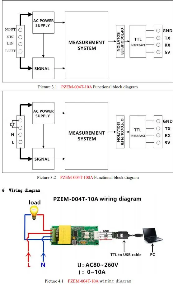


3 Functional block diagram
5 Other instructions
5.1The TTL interface of this module is a passive interface, it requires external 5V power supply, w
hich means, when communicating, all four ports must be connected (5V, RX, TX, GND), otherwis
e it cannot communicate.
5.2 Working temperature
-20’C ~ +60’C。
วิธีการชำระเงิน
ชำระเงินผ่านธนาคาร
MEMBER
LINK
▲
▼
รายการสั่งซื้อของฉัน
รายการสั่งซื้อของฉัน
ข้อมูลร้านค้านี้

ขายดีจริงจัง
สินค้าอีเล็คโทรนิกส์สำหรับทำโปรเจ็คต่างๆ รับสั่งซื้ออุปกรณ์จากต่างประเทศสำหรับบริษัทห้างร้าน นักเรียน นักศึกษา
เบอร์โทร : 087-151-4727
อีเมล : apisitmi@windowslive.com
อีเมล : apisitmi@windowslive.com
ส่งข้อความติดต่อร้าน
เกี่ยวกับร้านค้านี้
ค้นหาสินค้าในร้านนี้
ค้นหาสินค้า
สินค้าที่ดูล่าสุด
บันทึกเป็นร้านโปรด
Join เป็นสมาชิกร้าน
แชร์หน้านี้
แชร์หน้านี้
↑
TOP เลื่อนขึ้นบนสุด
TOP เลื่อนขึ้นบนสุด
สินค้าในตะกร้า ({{total_num}} รายการ)

ขออภัย ขณะนี้ยังไม่มีสินค้าในตะกร้า
ราคาสินค้าทั้งหมด
฿ {{price_format(total_price)}}
- ฿ {{price_format(discount.price)}}
ราคาสินค้าทั้งหมด
{{total_quantity}} ชิ้น
฿ {{price_format(after_product_price)}}
ราคาไม่รวมค่าจัดส่ง
➜ เลือกซื้อสินค้าเพิ่ม